Division of Environmental Quality Director: Art Goodin
Table of Contents
Introduction
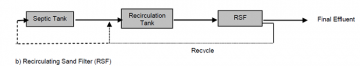
Figure 1: Recirculating Sand Filter
The basics of RMFs
Figure 2: General RMF Schematic
Implementing Optimization
Table 1: Potential Sampling Locations and Parameters to Monitor
Operational Improvements
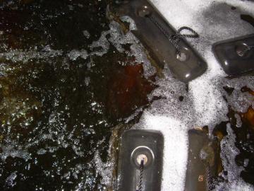
Figure 3: A hydraulically and organically overloaded recirculating sand filter
Inflow and Infiltration
Verification of System Design
Primary Treatment
Equalization Tank
Screened Outlets
Figure 4: Screened septic tank outlets
Recycle line
Figure 5: Recycle line to the Septic Tank
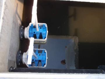
Recirculation Tank
Figure 6: Floating Media in the Recirculation Tank
Figure 7: Retrieving the media placed in the recirculation tank
Recirculation Ratio
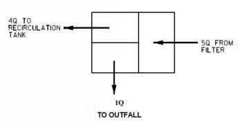
Figure 8: Traditional Recirculation Ratio
Chemical Dosing
Alkalinity
Table 2: Alkalinity Chemicals
Carbon
Table 3: Supplemental Carbon
Filter Bed
Figure 9: Media filters zoning
Figure 10: Two Recirculating Sand Filter Beds
Underdrains
Figure 11: Cross-section of a Recirculating Gravel Filter Underdrain
Figure 12: Blowers connected to the underdrain
Polishing filter
Innovative Technologies
Additional Assistance
Additional Resources
Table 4: Summary of Process Changes to Optimize RMF Operations
Introduction
Recirculating Media Filters (RMFs) using sand, gravel or other media provide advanced secondary treatment of primarily treated wastewater or septic tank effluent. They consist of a lined excavation or structure filled with media, typically uniform washed sand or pea gravel, which is placed over an underdrain system. The wastewater is dosed onto the surface of the sand through a distribution network and allowed to percolate through the media to the underdrain system. The underdrain system collects and recycles the filter effluent to the recirculation tank for further processing or discharge.
In Missouri, the first permitted RMF was constructed in 1974; however they gained prominence in the 1990s in southern and central parts of the state due to the cost effectiveness, ease of operations and smaller footprint than a traditional extended aeration plant for facilities less than 100,000 gallons per day (100,000 gpd). There are currently 599 RMFs in Missouri, with 87% of them being privately owned, which means they are not required to have a certified operator or conduct operational monitoring per 10 CSR 20-9 (unless they are regulated by the Public Service Commission). In an evaluation of discharge monitoring reports from 36 publicly owned systems that are required to have certified operators and conduct operational monitoring, the data showed that many facilities were on average operating near the current water quality standard for ammonia effluent limits of 1.4 mg/L for summer and 2.9 mg/L for winter.
In Missouri, the majority of existing RMFs are designed to remove biochemical oxygen demand (BOD) and total suspended solids (TSS). While the systems were designed for BOD and TSS removal, nitrification and some denitrification can occur. Nitrification converts the ammonia or ammonium present in wastewater through biological oxidation to nitrite followed by the oxidation of nitrite to nitrate. While nitrification is what the majority of facilities are attempting to achieve currently, it may be in a facility’s best interest to achieve nitrification and denitrification. Denitrification is the removal of the nitrogen from the wastewater, including the ammonia, total kjeldahl nitrogen (TKN), nitrate and nitrite.
This guidance is intended to provide facility owners and operators with guidance on optimization of RMFs in Missouri for ammonia treatment. It is in no way intended as a substitute for professional engineering consulting advice. While the scenarios described in this document may appear to provide solutions for some situations, users of this guide are urged to seek the advice of their own consultants and wastewater treatment professionals who can assess the unique circumstances and address specific facility conditions.
As stated before, the majority of existing systems were designed for BOD and TSS removal, which generally means they were designed for a hydraulic loading rate of less than five gallons per day per square foot (5 gpd/ft2) and a recirculation ratio of 4:1.
Properly designed, operated and maintained RMFs can produce effluent that is protective of water quality where instream assimilative capacity exists. On the other hand, aging and/or neglected systems can pose a threat to water quality. RMF facilities are encouraged to properly maintain facilities and actively work toward optimization of operations to achieve the highest attainable effluent quality.

The Basics of RMFs
RMFs employ a combination of physical, chemical and biological processes to produce effluent that may meet requirements for discharge to surface waters, depending on receiving water criteria. The “media” can be any of a number of physical structures whose sole purpose is to provide a surface to support biological growth. The media must be uniform in size as to prevent compaction and ponding of the filters. Commonly used media includes rock, gravel, sand of various sizes and textile media. The category of treatment referred to as media filtration includes a number of variations on the process. They can be broken down into subcategories based on how many passes through the filter the wastewater makes, whether the filter surface is open to the air or buried, and the relative size and type of the media (e.g., sand, gravel, textile or other).
The performance of a RMF system depends on the type and biodegradability of the wastewater, the environmental conditions within the filter and the design characteristics of the filter. Temperature affects the rate of microbial growth, chemical reactions and other factors that affect the stabilization of wastewater within the RMFs. Other parameters that affect the performance and design of RMFs are the degree of wastewater pretreatment, the media size, media depth, hydraulic loading rate, organic loading rate and dosing techniques and frequency.
In all cases, primary treatment of the raw wastewater to reduce the BOD and suspended solids content is required. Once settling is accomplished, the wastewater is applied to the filter surface in small doses, to alternately load and rest the media. As wastewater percolates down through the filter bed, it comes into contact with the bacterial film growing on the media. The media should have a high surface area to volume ratio, large enough voids to allow air filtration and to minimize fouling, UV resistance if exposed to sunlight and low solubility in water and acidic conditions.
The water is contained by an impermeable liner and collected in an underdrain. The underdrain pipe directs the water to a flow splitting structure, in which a portion of the flow can be diverted back to the recirculation tank for additional treatment, with the rest discharged as effluent. Where total nitrogen removal is desired, recirculation back through the recirculation tank provides contact between the nitrate-laden water and carbon-bearing influent in the presence of bacteria. Figure 2 below provides a typical schematic of RMFs.

Implementing Optimization
For optimal treatment to occur, operation and maintenance must occur on a regularly scheduled basis. Each facility should maintain an Operations and Maintenance (O & M) Manual developed at the time construction was permitted. The O & M Manual must be reevaluated and updated as items at the facility change (e.g., component replacement) and should be comprehensively reviewed and updated at least every five years.
Prior to any system optimization, the facility should conduct multiple sampling events on the wastewater prior to the septic tank, in the recirculation tank, and at the effluent for all parameters listed in the operating permit, plus alkalinity, total nitrogen (TN), chemical oxygen demand (COD) and dissolved oxygen (DO). The cost for sampling three times during different operating conditions is estimated to be about $3,500. Different operating conditions could include peak flows due to usage or from storm events, normal flow periods and low flow times. While additional sampling is a sizable expense, it will establish baseline conditions and provide information vital to identifying areas for improvement. In the table below are examples of the different locations in the treatment system that should be sampled and the parameters to sample.
|
Location |
Potential Parameters to monitor |
|---|---|
|
Influent |
Alkalinity, Ammonia, BOD, COD, DO, flow, pH, temperature, TN, total organic carbon (TOC), TSS |
|
Septic tank effluent |
Alkalinity, Ammonia, BOD, flow, pH, temperature, TN, TOC, TSS |
|
Recirculation Tank |
Alkalinity, Ammonia, BOD, COD, DO, flow, pH, temperature, TN, TOC, TSS |
|
Recycle Line |
Alkalinity, Ammonia, COD, DO, flow, pH, temperature, TN, TOC |
|
Discharge effluent |
Alkalinity, Ammonia, BOD, flow, pH, TN, TSS |
The following are examples of operational improvements and system modifications that an existing facility may make that will facilitate ammonia treatment.
Operational Improvements
Proper operations and maintenance is key for recirculating media filters. Review of discharge monitoring reports shows facilities with a certified operator regularly on-site to conduct operational monitoring and operations and maintenance had better effluent quality results than systems without a qualified operator on-site regularly.
A key issue often overlooked is that if it is hydraulically or organically overloaded, a RMF plant will usually not work. Most existing RMFs were designed based upon hydraulic loading. With the advent of low flow fixtures, other water conservation measures and garbage disposal systems, hydraulic flows may have decreased or remained the same, but the organic loading will have increased. This is where influent monitoring of all parameters, including flow measurements, prior to the septic tank would help identify any possible problems, they become noticeable and more costly to address, such as the Figure 3 below. This facility was significantly hydraulically and organically overloaded; while in most cases, the overloading would not be this extreme, ponding or clogging may start to occur, along with effluent discharge samples increasing in concentration. The facility below (Figure 3) has since been replaced and redesigned with appropriate hydraulic and organic loadings.

Regularly scheduled operations and maintenance is essential for recirculating media filters. At a minimum, the facility should follow the manufacturer’s recommendations for scheduled cleanings, replacement or even checks for the various components of the system. The department has developed a guidance, Recirculating Media Filter Operation and Maintenance, to provide more in-depth, detailed discussion of RMF components and type of maintenance needed to keep the system operating at its best. In general, the operation and maintenance activities most likely to lengthen the facility’s operational life and improve its performance include the following:
- Regularly check the amount of solids in the primary treatment unit (i.e., septic tanks).
- Schedule pump outs of the primary treatment as needed, but on a three to five year cycle maximum.
- Regularly check and remove the solids from the recirculation tank.
- Remove vegetation from the filter bed; however, avoid chemicals to kill vegetation.
- Check spray height to look for clogged dosing panels.
- Inspect and test pumps, switches, floats, timers and alarm system at each maintenance inspection, repair as needed and cleaned at least annually.
- If there is a flow equalization tank, regularly check and remove solids from the tank.
- Do not use a Rototiller or other garden equipment to mix up the media filter beds.
- Test for alkalinity in the influent, the recirculation tank, and in the effluent to make certain denitrification is not inhibited.
- Divert stormwater from the filter bed.
- Replace approximately-sized media, as necessary, to keep at least 36 inches in place.
Inflow and Infiltration
Inflow and infiltration (I/I) is the entrance of water into the treatment system. Inflow is inappropriate connections into the collection system, examples include sump pumps and roof drains. Infiltration is groundwater entering the collection system through broken pipes and pipe joints. Inflow and infiltration can increase the amount of water entering the system, dilute the wastewater entering the treatment system and can increase the costs of treatment. A treatment system receiving flows greater than its peak design, can experience short-circuiting in the septic tank, recirculation tank and may cause the filter beds to have ponding or experience wash-out of solids from the tanks, which can clog the filter. To prevent inflow and infiltration into the system, a thorough evaluation of the collection system is necessary and to replace or repair broken pipes or disconnect sump pumps and roof drains from the collection system. The Department has developed guidance for facilities to capacity, management, operations and maintenance plan to help address the maintenance needs a community may face in addressing the impacts of inflow and infiltration in their system. The Capacity, Management, Operations, and Maintenance (CMOM) Plan Manual Guidance - PUB2574 is available on the department’s website, along with an editable CMOM template.
Sampling of the influent water into the septic tank can identify if inflow or infiltration is impacting the influent wastewater characteristics.
Verification of System Design
Besides good operations and maintenance, a facility may need to optimize the treatment system to improve the facility’s effluent. As mentioned above, low flow and water conservation measures may have increased the organic loading while decreasing the hydraulic loading into the system.
Before trying the system modifications listed below, especially for systems serving a recreational area, multiple sampling events of the influent and effluent is crucial as the facility may not be receiving wastewater within the original design parameters and the modifications listed below may not provide optimization. High strength wastes require more contact time with filter media and more frequent dosing. For all optimization system modifications, the facility should work with an engineer and/or a certified operator to keep the system operational.
For systems serving recreational areas, the design may have been based on the hydraulic loading rather than the organic loading. To verify the design basis of the plant is accurate, sample the flow from the septic tank before it enters the recirculation tank for the BOD loading contributions. For ammonia removal, the organic loading should be no more than three-thousandths of a pound of applied BOD per square foot per day (≤0.003 lbs BOD/gpd/ft2) and the hydraulic loading should be less than three and half gallons per day per square foot (≤3.5 gpd/ft2).
Primary Treatment
Verify the septic tank provides a minimum of 36 to 48 hours of detention time at the peak hourly flow. If the septic tank is not appropriately sized, replace the tank with a tank that can provide at least the minimum detention time at peak flow or add another tank in series. Replacement with a larger septic tank would require a construction permit, but not an operating permit modification.
Equalization Tank
If the primary treatment tank does not have a minimum of 36 to 48 hours of detention time, or if the flows are generated over a compressed time, adding an equalization tank after the septic tank is recommended. A compressed flow is a flow rate that will discharge the average design flow volume to the septic tank in under 12 hours, such as in a school. When utilizing or adding a flow equalization tank, the tank should be sized based on a hydraulic analysis of the system that distributes the compressed flow and eliminates surcharging of the recirculating media filter. A hydraulic analysis consists of monitoring hourly flows over a 24-hour period over multiple days and/or operating conditions to identify the peak flow conditions, potential hydraulic overflows, or when surge conditions exists. A flow totalizer will not show the different conditions that exist within the facility. Flow equalization should be sized based on a hydraulic analysis of hourly flows.
In all cases, flow should be pumped to the recirculation tank at a rate that equalizes flow over 24 hours. It is recommended that a timer with a high-level override control should operate the pumps in the flow equalization tank.
Screened Outlets
Screening the outlets of the septic tank lessens the amount of or prevents solids from entering downstream treatment components, specifically the recirculation tank or the media bed. Removal of solids allows for the media filters to treat the wastewater more efficiently. The screened outlets will need to be regularly cleaned and maintained to function properly.
Recycle Line
Recirculating water from the media bed back to the septic tank will create an anoxic zone, especially if the septic tank is located near the media bed. Residual dissolved oxygen in the recycled water is quickly depleted, creating anoxic conditions. According to EPA, returning water to the septic tank increases the total nitrogen removal to approximately 50%. When sufficient carbon remains, denitrifying bacteria is favored for consuming the available nitrogen in the wastewater and returning some alkalinity to the system.
A flow splitter dividing the recirculated water between the septic tank and the recirculation tank may provide additional benefit by creating an anoxic zone that returns some alkalinity and by gaining the benefits of the recirculation tank. Pilot testing a recycle line configuration to verify treatment improvements and optimize the return ratio flow splits is recommended prior to installing a permanent recycle line.
Recirculation Tank
The recirculation tank is part of the treatment process to remove BOD, TSS and nitrogen from the wastewater. A recirculation tank collects the water from the primary treatment system and mixes it with the treated wastewater from the media filter. The recirculation tank often contains the dosing pumps. Verify the recirculation tank is not short-circuiting as that can inhibit treatment. In pilot testing, adding aeration alone to the recirculation tank did not improve the removal of ammonia.
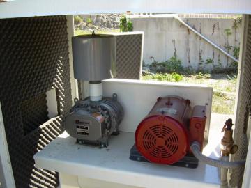
A facility in Missouri conducted a pilot testing by means of adding floating media and aeration to the recirculation tank. The added media in the recirculation tank provided additional surface area for the bacteria in wastewater to attach. Adding the floating media with aeration to the recirculation tank showed almost a 98% reduction in their facility’s effluent ammonia. The trade-off for increased treatment did come with increased operation and maintenance costs related to cleaning the filters and pumps more frequently. The pictures are from the pilot project. The first picture shows the media in the recirculation tank while the plant was operational.
The second picture is the operator retrieving the media from the tank for maintenance.
Recirculation Ratio

The recirculation rate is the portion of the wastewater effluent that is delivered back into the system compared to the wastewater effluent that is to be discharged. A potential system change to consider is increasing the recirculation ratio. Most RMFs were designed and set up to recirculate 80% of the flow and discharge 20% (i.e., 4:1 ratio), as seen in Figure 8 below. This means five times the influent flow is actually going through the RMF. Results have shown increasing the ratio to 5:1 or 6:1 minimizes the dissolved oxygen present and maximizes denitrification.
The higher recirculation ratio usually provides better treatment, but it can increase costs for upsized tankage and energy in pumping. Other impacts with high recirculation ratio include depletion of alkalinity due to complete nitrification, low pH which can impact treatment components including allowing filamentous organisms to form and clog the system, and potential need for supplemental carbon for denitrification. If the facility experiences periods of extreme low flow, treatment could be inhibited if the system does not utilize flow equalization. Recirculation rates are not recommended above 8:1.
Chemical Dosing
Depending on the characteristics of the wastewater, the addition of chemicals may be necessary to facilitate ammonia removal, nitrification and denitrification. Supplemental alkalinity or carbon are the most common additions to RMF systems to improve treatment. Depending on the chemicals utilized, the supplemental addition of chemicals intended to change alkalinity and/or add carbon may represent a new pollutant of concern and trigger antidegradation requirements.
Alkalinity
Alkalinity is the water’s capability to neutralize acid. For nitrification to proceed, the wastewater must have sufficient alkalinity to allow the biochemical conversion from ammonia to nitrate to occur. For a treatment system to remove ammonia, there needs to be approximately eight milligrams of alkalinity, as CaCO3, to consume one milligram of ammonia (8 mg of CaCO3:1mg NH3). If the facility is also doing phosphorus removal, then testing the alkalinity in the effluent is a necessity as both phosphorus removal and nitrification consume alkalinity. If the facility is doing denitrification, some alkalinity is returned to the system.
To prevent impacts to the pH, a residual alkalinity of at least 50 milligrams per liter (50 mg/L) should be present in the effluent. If the residual alkalinity is not present, the pH can drop and impact the treatment capabilities of the system. Supplemental alkalinity dosing should occur in the recirculation tank.
There are a variety of chemical compounds that can be used to supplement the existing alkalinity in the wastewater, each with advantages and disadvantages.
|
Chemical (Common Name) |
Chemical Formula |
Advantages |
Disadvantages |
|---|---|---|---|
|
Sodium hydroxide (Caustic soda, caustic) |
NaOH |
Ease of handling; lower annual maintenance costs |
Higher chemical cost; crystalizes at temperatures below 55°F |
|
Calcium hydroxide |
Ca(OH)2 |
Small amount (3-5% by weight) needed to treat |
Must be slurried before use; raises the pH to above 12 |
|
Calcium oxide (Quicklime) |
CaO |
Cheaper than calcium hydroxide |
Must be slaked at 248-356°F, scaling issues, labor intensive process, high operation costs |
|
Magnesium hydroxide |
Mg(OH)2 |
Does not raise the pH above 10.5 |
Scaling issues; costs for chemical are regionally driven; struvite formation |
|
Sodium Carbonate (soda ash) |
Na2CO3 |
Can be dissolved onsite from dry product |
pH at 12 |
|
Sodium bicarbonate |
NaHCO3 |
Maximum pH of 8.3; can be dissolved onsite from dry product |
High chemical cost, higher operation and maintenance cost |
Carbon
Carbon is necessary for denitrification to occur. While there are internal processes that can return carbon to the process, if high levels of nitrogen are present in the recycle line or the primary effluent, the ability of internal carbon sources to remove nitrogen is limited and the addition of an external carbon source is usually necessary. If using a RMF after a septic tank effluent pumped (STEP) sewer system, or where the influent BOD to TKN ratios are 3:1 or less, supplemental carbon will certainly be necessary for ammonia and total nitrogen removal.
The influent dissolved oxygen entering the system needs to be minimized or dosing additional supplemental carbon will be needed to lower the dissolved oxygen and create anoxic conditions. Complete mixing with no dead zones in the anoxic area is necessary. Minimal dissolved oxygen can be obtained by limiting turbulent influent pumping conditions to the filter.
There are a variety of chemical compounds that can be utilized to supplement carbon in the wastewater, each with advantages and disadvantages.
|
Chemical |
Chemical Formula |
Advantages |
Disadvantages |
|---|---|---|---|
|
Methanol |
CH3OH |
Low freezing point; usually the cheapest cost; most commonly used |
High operations and maintenance cost; price volatility; explosion hazard; toxicity concerns; requires grounding and ventilation |
|
Ethanol |
C2H6O |
None known |
High operations and maintenance cost; hazardous; highly flammable; same handling considerations as methanol higher biomass yield; |
|
Glycerin |
C3H8O3 |
Safer than ethanol or methanol; lower capital cost compared to methanol; by product of biodiesel production |
Expensive; Viscous in colder weather; impurities |
|
Acetic Acid |
CH3COOH |
Safer than ethanol or methanol; readily available; does not require acclimation period; variety of solution strengths available |
Expensive; can be corrosive, potentially flammable, large storage volume; may need heated storage in colder areas; hazardous material concerns at high solution strengths |
|
Sodium or Potassium Acetate |
CH3COONa or CH3COOK |
Available in crystalline or powder forms; non-hazardous |
Handling and storage concerns, even at moderate temperatures; high cost relative to other carbon sources |
|
Sugar or Carbohydrate based Solutions |
Glucose Sucrose Tri and /or polysaccharides Molasses Corn sweeteners |
Non-hazardous; widely available; commodity product |
Higher yields of biomass; Higher freezing point than methanol; can degrade over time; Molasses contains nitrogen and phosphorus-so must evaluate impact to the system; |
Filter Bed

Good maintenance of the existing filter bed is key in optimization. If necessary, replace missing media and replace sides or add berms to prevent stormwater from entering. Below is a typical schematic of how a filter bed would be set up with multiple zones. The filter media of a sand and gravel filters should be 36 inches deep.
Other options in the filter bed include replacing the media with a finer grain media or synthetic media, which could increase the surface area available for treatment. The ideal media has a high surface area to volume ratio, large enough voids to allow rapid air filtration and minimize fouling, UV resistance, low solubility in water and acidic conditions and be cost-effective and locally available, if possible.
To reduce the hydraulic or organic loading, consider increasing the size of the filter beds or adding additional zones. This may increase the capital cost for construction of the beds.

Verify the distribution network in the filter bed is not clogged. If the filter bed is clogged, replacement of media may be necessary. Do not use a Rototiller to break up the media bed, as this will cause more problems with the treatment system.
If possible, consider adding a cover to the filter bed. If the filter bed can be completely enclosed, similar to a package synthetic media system, it would prevent stormwater from entering the system and provide some insulation to the wastewater, which would allow the bacteria to continue working when the temperature drops. If the entire bed cannot be enclosed, even adjusting berms of the filter bed and partial covers will help minimize or prevent stormwater from entering the system.
Underdrains
Underdrains collect the water that filters through the media into pipes and sends it back to the flow splitter through the return line. The flow splitter would then send some of the water to the discharge pipe and some of the water back to the primary treatment system or the recirculation tank. The underdrain system should be designed to prevent sediment and media from entering the pipe and clogging it. Verify the underdrains are fitted with cleanouts.

In a pilot test in southern Missouri, using the underdrain system and a blower to add air to the filter improved ammonia removal, by increasing the dissolved oxygen in the filter bed. The facility ran the blower continuously cycling, with it being off for 15 minutes every four hours. The facility saw a reduction in their effluent ammonia of almost 90%.
Polishing Filter
Polishing filters are often an intermittent media filter designed for tertiary treatment. The tertiary polishing filter may continue to reduce solids present and depending on the loading, ammonia in the system. The polishing filter would be placed on the discharge line, not the recycle or return lines. The backwash from the polishing filter would need to be returned to the recirculation tank. Polishing filters are not common on RMFs.
Innovative Technologies
An innovative technology that has been proposed is the construction of a moving bed biological reactor (MBBR) after the recirculating media filter. While MBBRs are a proven technology in Missouri for secondary treatment of BOD and TSS, this is still considered innovative when used as a tertiary treatment. Other innovative technologies may exist to further treat wastewater in a RMF system. If the design involves construction or utilizing an existing technology in a unique way, permittees should follow the department’s Approval Process for Innovative Technology - PUB2453 fact sheet.
Additional Assistance
The department’s Operator Certification Program offers classes on the operations and maintenance of RMFs. Operators of RMFs are encouraged to attend this specialized course for additional information on improving the operation and maintenance of their facility. Visit Operator Certification Program’s website to find trainings near you.
A Wastewater Specialist is available at your regional Missouri Department of Natural Resources office to provide training, troubleshooting, and technical assistance to public drinking water or wastewater system operators. Visit the department's regional office webpage to find the office serving your area.
Additional Resources
- Recirculating Media Filter Operation and Maintenance - PUB2738
- Approval Process for Innovative Technology - PUB2453
- EPA’s Recirculating Sand Filters
- Recirculating Sand Filters guidance (Virginia)
- Recirculating Sand Filters guidance (Iowa)
- Washington Department of Health and Department of Ecology
- National Environmental Services Center (NESC)
|
Technology |
Benefit |
Risks |
Dependents |
Complimentary Treatment |
Capital Cost |
Maintenance Requirements |
Footprint |
DNR Permits |
|---|---|---|---|---|---|---|---|---|
|
Example |
Reduces N, BOD, improves operation |
Potential risks with uses-cost, chemicals, reduces life cycle |
Other requirements for the technology to function |
Other treatments that would work well in conjunction with technology |
Low($), Medium ($$), High ($$$) |
Low/Medium/High |
Change in overall footprint at the site |
CP required, OP mod required, OP notification, no change to OP |
|
Blower to the underdrain system |
Reduces ammonia concentration |
Increases dissolved oxygen in the return water |
May need more electricity |
|
$$ |
Medium |
No change, may need more electricity |
No change to OP, no CP required |
|
Floating media in the recirculation tank |
Reduces ammonia concentration |
Increased maintenance |
May need aeration |
|
$$-$$$ |
High |
No change |
CP required, no OP modification-facility description update |
|
Filter bed increase |
Reduce organic and hydraulic loading |
May need land disturbance permit; reduced loading may not get be enough to achieve desired results |
|
Recirculation ratio, recycle line to primary treatment |
$$$ |
Low |
Large change in site footprint demands due to changes in piping, pumping and dosage |
CP required; no OP modification-facility description update |
|
Replace filter media |
Possibly increase surface area |
May not be enough to achieve desired results |
|
|
$$$ |
Low |
No change |
CP required; no change to OP |
|
Recycle back to primary treatment |
Creates anoxic zone-denitrification, total nitrogen removal |
May need supplemental carbon |
New piping back to primary treatment, |
Increased recirculation ratio |
$-$$ |
Low |
No change |
CP required |
|
Increase recirculation ratio back to recirculation tank |
Increase nitrification |
May need supplemental alkalinity; may increase equipment sizing |
May need larger pumps |
Recycle back to primary treatment; Supplemental alkalinity |
$-$$ |
Low |
May increase footprint if needing to increase equipment size |
CP required if upsizing equipment; otherwise, no CP or OP required |
|
Filter bed cover |
Reduce water entering system; insulates water |
Odors; may not increase treatment capabilities, may increase maintenance |
|
|
$$$ |
Low-Medium |
No change |
No CP required; No change to OP-facility description update |
|
Polishing filter |
May reduce solids and ammonia |
Increased maintenance, cost for chemicals, if applicable |
|
|
$$-$$$ |
High |
Space for filter, piping and pumping |
CP required, no OP-facility description update |
|
Supplemental alkalinity |
Increase ammonia removal |
Chemical costs, safety requirements for handling and storage |
Pumps and dosing equipment, safety requirements |
Recirculation ratio, supplemental carbon source, |
$-$$$ |
Medium-High |
Space for dosage, storage and pumps |
CP and OP required depending on chemicals utilized and process changes |
|
Supplemental Carbon source |
Increases denitrification treatment |
Chemical costs, safety requirements for handling and storage |
Pumps and dosing equipment, safety requirements |
Supplemental alkalinity, return line to primary treatment |
$$-$$$ |
High |
Space for storage and dosing pumps |
CP and OP required |
|
Screened outlets |
Reduces solids into the recirculation tank |
May not improve ammonia removal |
|
Recirculation ratio, increase filter bed size, recycle line back to primary treatment; floating media in the recirculation tank |
$ |
Low |
No change |
No change to OP, no CP required |
Nothing in this document may be used to implement any enforcement action or levy any penalty unless promulgated by rule under chapter 536 or authorized by statute.
For more information
Water Protection Program
Division of Environmental Quality
P.O. Box 176
Jefferson City, MO 65102-0176
United States